Aircraft
Certification Service Washington, DC U.S. Department of Transportation Federal Aviation Administration
CE-14-03
November 15, 2013
This is information only. Recommendations
aren’t mandatory.
Introduction
This Special Airworthiness Information Bulletin (SAIB) informs
registered owners/operators of all airplane models of Univair Aircraft
Corporation/under Type Certificate Data Sheets TCDS (A-718/Mooney,
ERCO/415C, 415CD) and A787 (ERCO, 415-D, E, G, Forney, F-1, F-1A, Alon,
A-2, A2-A, Mooney, M10) of an airworthiness concern. Specifically, this
SAIB provides and references procedures to inspect and repair or
replace, as necessary, affected airplanes with main wing spars showing
evidence of inappropriate modifications and/or holes with or without
cracks.
At this time, this airworthiness concern has not been determined to be
an unsafe condition that would warrant airworthiness directive (AD)
action under Title 14 of the Code of Federal Regulations (14 CFR) part
39.
Background
During the course of investigating an accident on an Ercoupe 415-D
airplane, an inappropriate modification was identified. The
inappropriate modification was an additional hole drilled and tapped in
a location that affected the radius of a flanged member on the main
wing center section spar. The probable cause leading to the accident
was identified as the pilot’s exceedance of the design stress
limitations of the airplane. Although it was not cited as a probable
cause of the accident, the specific location where this hole was
drilled can lead to a reduction in strength of the affected structure.
The focus of this SAIB is to look for these types of modifications and
any cracking that may result from these modifications. In addition, as
a result of the investigation into this particular accident, the FAA
has identified concerns with the airspeed and flight control systems,
which were addressed in Airworthiness Directive (AD) 2012-08-06.
Recommendations
The FAA recommends the following:
Use visual inspection methods to detect inappropriate modifications
and/or unfilled drill holes. In addition, correct any cracking that may
be a result from these modifications and/or unfilled holes.
When inspecting the front and rear wing spars, wing spar caps, and spar
web areas in the wing center section for wrinkles and skin cracks, keep
in mind that the inappropriate modifications could exist from prior
ownership and may have been overlooked. There have been some airframes
in the past that were modified by field approval for installation of
Cessna 150 airplane seats and seat rails that required attachment holes
in the spar caps. Visual inspection is the primary means of examining
the airplane structure for the presence of cracks and other anomalies
that can lead to reduced structural strength. Essential aids for visual
inspection include a powerful flashlight, mirror with a ball joint, and
a magnifying glass. A 10-power magnifying glass is usually sufficient
to confirm the existence of suspected cracks. A preliminary inspection
should take place to check for overall cleanliness of the area,
presence of foreign objects, deformed or missing fasteners, and
security of parts, corrosion, and damage. Use a 10-power magnifying
glass to confirm the existence of a suspected crack. If this is not
adequate, use other NDI techniques, such as liquid dye penetrant, to
verify the cracks. After inspection and/or repair(s), treat the area
with a corrosion preventative compound. If during any center spar area
inspection, wrinkles, cracks in the spar cap or spar shear web, or
inappropriate modifications, are found to exist, repair to restore
structural strength before further flight. At this time, there are no
approved repair instructions from the manufacturer. You may submit
proposed repairs to the Denver aircraft certification office (ACO) for
evaluation and approval using the contact information in this SAIB. We
recommend consulting with Designated Engineering Representatives (DERs)
authorized in the structural repair disciplines appropriate to this
aircraft type before submitting the proposed repair to the Denver ACO.
In some cases, spar replacement may be the only solution.
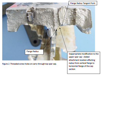
If during any inspection open holes are found to exist in the spar cap
structure as shown in Figure 2, or in the spar web areas; fill the open
hole locations using the following guidance documents: Advisory
Circular (AC) 43.13-1B Section 4-57, Advisory Circular 43.13-2B,
Chapter 1, Paragraphs 106-110, and Metallic Materials Properties
Development and Standardization (MMPDS-04) April 2008, Chapter 8, Page
8-13. Monitor this repair under standard aircraft inspection intervals.
If it is necessary to drill an open hole location to obtain a clean
hole for rivet installation, the final hole diameter should not
intersect the tangent point to the flange radius as shown in Figure 2.
Avoid drilling holes larger than 10-percent of the existing cross
sectional area; or otherwise decreasing the effective tensile strength
areas and/or edge distance of wing spar cap strips, web areas, or
highly stressed tensile areas. If these criteria cannot be satisfied,
further repair as noted above will be necessary.
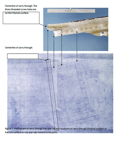
Note: See Figures 1 and 2 below for information of an example of
an inappropriate modification performed on a spar cap. This particular
spar cap most probably failed due to the pilot exceeding the design
stress limitation of the airplane. A self-tapping fastener had broken
off in one threaded hole and another had been threaded right into the
radius of the flanged member of the spar cap (the “T” junction). The
location of the hole in the spar cap T junction can lead to a reduction
in structural strength of the affected structure.
For Further Information Contact
Roger Caldwell, Aerospace Engineer, ANM-100D, 26805 East 68th Avenue,
Room 214, Denver, CO 80249; Phone: (303) 342-1086; fax: (303) 342-1088;
e-mail:roger.caldwell@faa.gov.